You will need
- - Arduino UNO or equivalent;
- - Bluetooth module HC-06 or equivalent;
- - the motor driver L9110S or equivalent;
- - tracked platform for the tank Pololu Zumo or equivalent;
- a piece of fiberglass the size of the Board or Arduino shield for prototyping;
- - 2 motor, suitable to the selected chassis;
- - 2 LEDs ("lights") and 2 180-220 Ohm resistor;
- - batteries (1 "Crown" or penlight 4-6);
- - connecting wires;
- - soldering iron;
- computer;
- 6-10 bolts M2,5.
Instruction
1
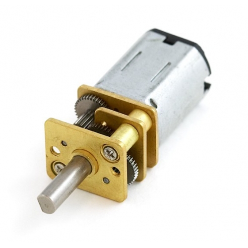
Fasten the motors to the chassis. I use two 12 mm motor with gear bought in Ampere. They fit perfectly to my chosen lug roboblather Pololu Zumo.
2
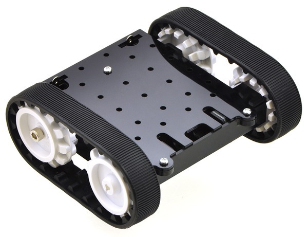
Collect crawler chassis according to the accompanying instructions. Very easy going in 10 minutes. This is the basis for our future vehicle. Please note that this chassis is equipped with a compartment for 4 AA-batteries. Will need to bring 2 wires "+" and "-" output to power all our design. On wire napati connector suitable for Arduino. It will be easier to connect power to the Board. If you are using another platform, you need to find a place to put the battery case and lead wire for power supply Board Arduino.
3
Fasten charge the Arduino Board to the chassis. Fasteners on roboblather not align the holes with the mounting holes on the Arduino UNO. So I make an extra platform made of fiberglass, which is fixed to the chassis with screws M2,5 and then bolted to her cost 4 same bolts.
4
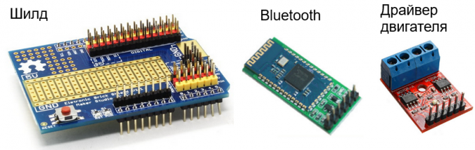
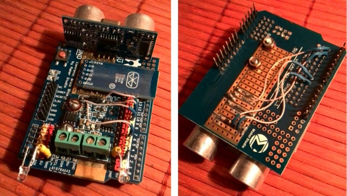
I think how to fix Bluetooth module, motor driver and "lights" on the chassis, then it's easy to connect to Arduino. I use a special card, or shield, (Electronic Brick Shield), such as in the photo. But it could be any other shield or even just a homemade Board. Fixed driver engines on Silde with bolts, pre-drilled Silde in the appropriate hole. Looking to drill not to damage the conductors need if you work with the shield. And caution: the bolt is metal, you can accidentally make a circuit. So around the drilled holes with a sharp knife remove the unused conductors. Under the nut and under the bolt head puts not carrying current goals.
5
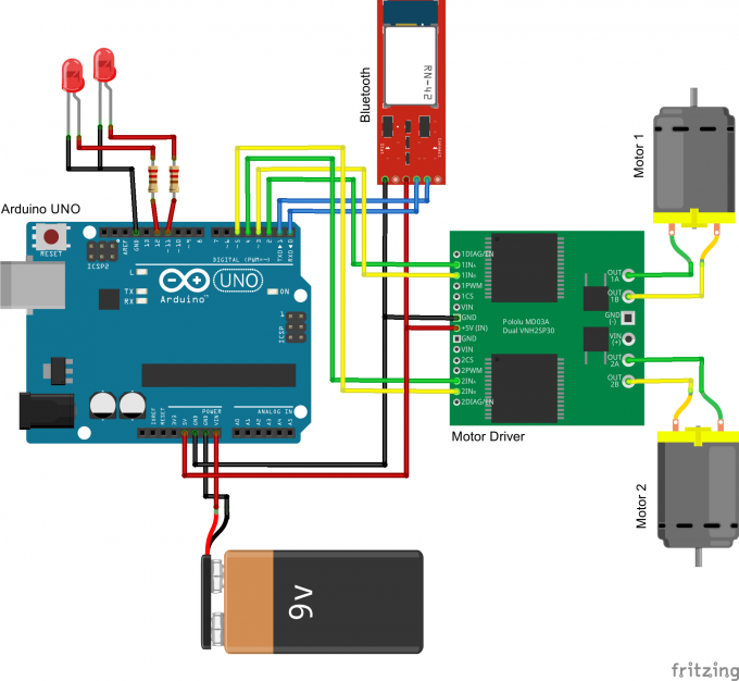
Now the most difficult and responsible. We have to collect all according to the pattern. Connect the Rx pin of Bluetooth module to Tx pin of Arduino, the Tx pin of module to Rx Arduino GND - ground Arduino, VCC to Arduino 5V (or 3.3 V - it depends on what you use the BT module). Here it is possible to use soldering or connecting wires with special tips of the type "Dupont".
To control two motors used 4 output of the motors ' driver + 2 supply. So take any 4 free digital pins of the Arduino and connected to the control terminals of the motor driver. Specific rooms will be set later in the program, so now it is not critical.
Finally connect the led anodes through the resistors is about 200 Ohm for any two remaining free Arduino pins and the cathodes to GND.
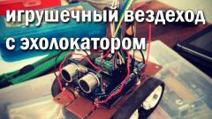
6
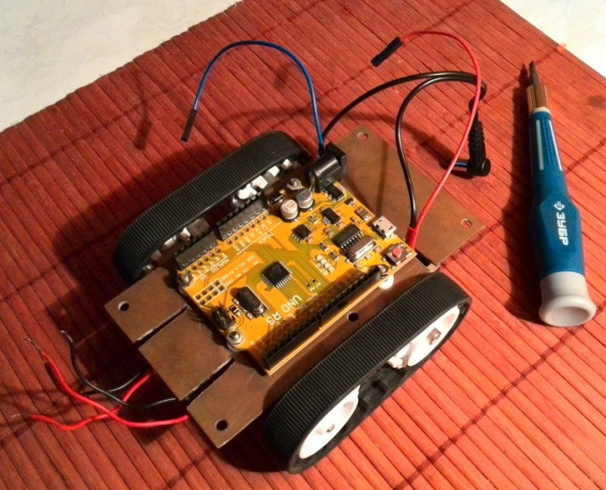
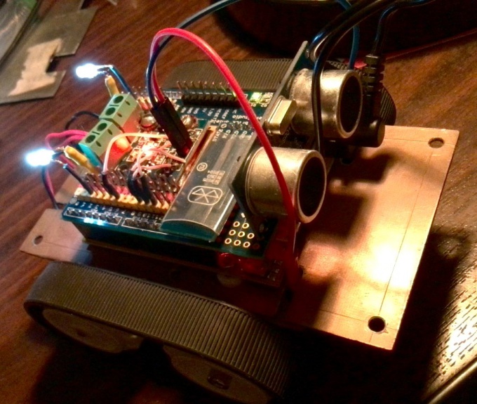
The result should be something like what is shown in the photo. I also present here the ultrasonic rangefinder to continue to give the Rover a "vision" and the ability to move independently. But that's for later. In this embodiment of the vehicle you have to Silde the sonar will not.
7
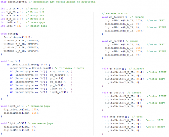
Now let's write the sketch (program) for the Arduino and upload it to the memory of the microcontroller. The program is very simple and is shown in the photo. Uploaded the sketch in a standard way. How it's done we have already discussed in a previous article. All the involved pins in the program correspond to the above connection scheme.
8
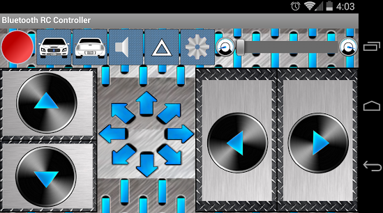
Download the program for managing our Rover. It's called "Arduino Bluetooth RC Car", and available in the market applications Google Play. Given the QR code leads to the app download page in Google Play.

9
After uploaded the sketch, then disconnect Arduino from the computer and connect the shield to our Arduino. Crucial moment: the first time to our vehicle! If everything is connected correctly, it should light up LEDs on Arduino and motors driver, and the led on the bluetooth module should flash rapidly.
10
Connect to the Rover via Bluetooth. To do this, run the program Arduino Bluetooth RC Car. When you run it will ask permission to enable bluetooth when not enabled. Allow. Click the button with the gear. The bottom menu will appear, click "Connect". You will see a list of paired with your smartphone devices as well as available nearby devices. One of these devices will be our Rover. Select it from the list. You are prompted to pair with the device and enter the code. This is usually 0000 or 1234, depending on what bluetooth module you used.
On successful pairing, the led on the module will blink with a frequency of approximately once per second, and the indicator in the upper left hand corner will be green. The smartphone will remember it, and code more, you need not.
Now you can try what we did. The Rover needs to drive forward and backward, turn left / right and also turn on and off lights.
11
If the command "Forward" the vehicle turns or travels back, then mixed up the wires to the motors. Swapping the yellow and green wires from the driver to the engine (in the diagram above), make sure that the vehicle went to the right place. If you have questions, write them in the comments!