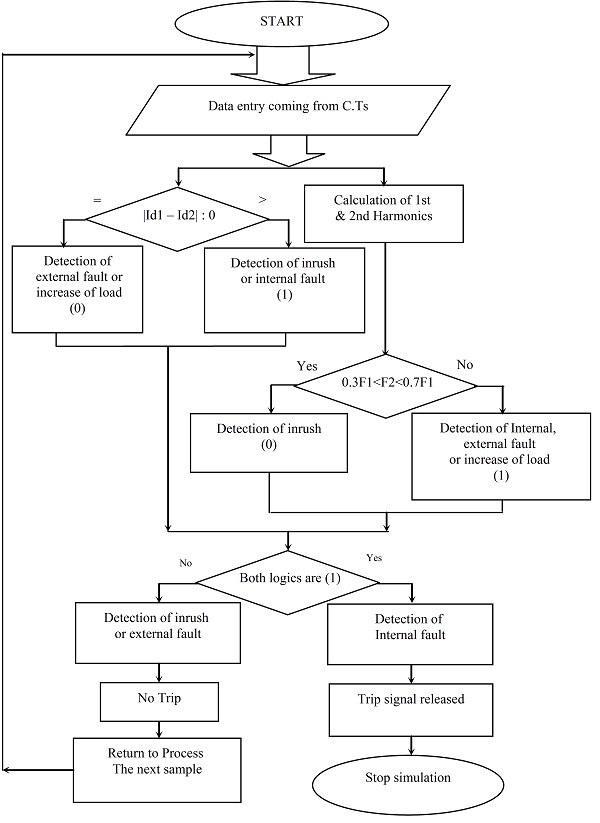
Organization flowchart
Graphical model algorithm is needed in order to look at the sequence of actions and thoughts to cover it all. It is known that the human brain is much better to solve the problem, if is the situation together, and block diagram is the perfect way to describe thus the algorithms for programming.
All blocks in the block diagram are interconnected by lines denoting relationships between them.
Study the block diagrams included in the compulsory program on the subject of computer science in high school. Description of this technique can be found in textbooks. As the use of flow charts makes programming easy, almost every blog that teaches readers to write the code also talks about this method.
Elements of block diagrams
Elements of a flowchart are geometric shapes, inside which you write the code or description of action. Scheme always starts with an elongated oval. It means the beginning or the end of the program, as well as the start or end functions (call and return). In a broader sense, we can say that this is the beginning and the end of the problem.
The rectangle is used for transfer operations, arithmetic or assignment. This action block.
Rhombus is a logical block, which contains the condition. It means testing for a condition, then branching occurs. Areas of branching can be as two (the design of the "if-then"), and several (usually in programming languages this construction is described by the word "case")
Rectangle with pillars at the sides of the block predefined process. It describes how to call subroutines and lists the variables that are passed at the same time. For example, as indicated by a function call.
Parallelogram – block input/output data. It lists the data you want to send to the output device or to the input device.
Hexagon, stretched horizontally. This figure represents the cycle. Inside is written the initial value of the variable cycle, its pitch and the exit condition. This unit can be divided into two halves, then the first to spell the beginning of the cycle, and the second end and is placed in the middle.
Features of the application block diagrams
To describe the operation of the applications written in the object approach, UML diagrams are used.
The block diagram is only applicable for those programming languages that are based on the structural approach. For artificial languages, for example, for low-level, this method of the description of the algorithm will not work. Similarly, if you write the object language within the paradigm of object-oriented programming, the interaction between objects using block diagrams to describe will not work. For such cases, there are other ways of visualizing the algorithm.