Instruction
1
Carefully review the sheet format. The scale should be indicated in the lower right corner of the sheet in the appropriate column. In mechanical engineering, instrumentation is often used scales such as 2:1, 4:1, etc. This is to ensure that the drawings of small parts with all the applied dimensions, cuts and sections could be easily read by the engineer, foreman or worker.
2
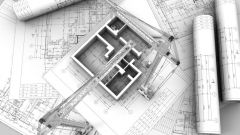
Construction drawings use a scale reduction, for example, 1:200, 1:400. Often for drawings certain types of buildings or buildings the designer is obliged to apply certain scales. The scale should also be included in the sheet format or the drawing.
3
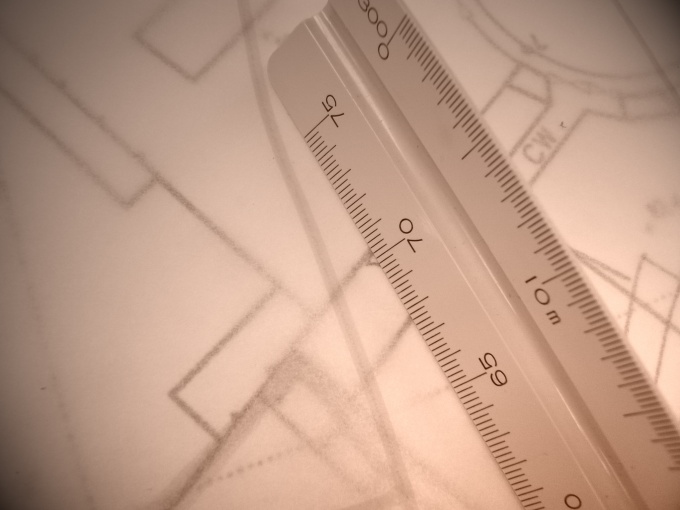
If you can't find the scale on the drawing, try to determine it yourself. For this you need to know what kind of object is depicted in the drawing and its dimensions. If the drawing size is not marked but you have to measure it using a Vernier caliper, ruler or tape measure.
4
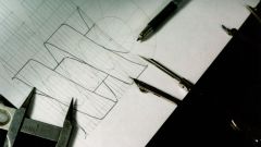
Locate on the drawing the view of the part on which are plotted dimensions. Place a ruler or tape measure to the dimension line of one of the dimensions and measure it's length. In the drawing it looks like a segment with arrows on the ends and a numeric value of size in the middle.
5
Compare the result with a numeric value. To do this, divide the result by a numeric value. For example, you received a value of 16 mm, and the dimension 8 is written. Dividing values, you will receive the number 2, this will be the scale of the increase, because the measured interval was greater than the value of the size in 2 times.
6
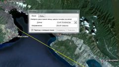
If you can't find a scale construction drawing, try to figure out the dimensions of the designed or existing buildings. To estimate the real size of the building, estimating the number of floors in it, the height of the ceilings, etc. Then measure the height of the building depicted in the drawing, and compare the values. Always keep in mind that the dimensions on drawings are given in millimeters.