You will need
- - soldering iron, solder and neutral flux;
- - multimeter;
- - power source;
- - resistors.
Instruction
1
If the optocoupler, the serviceability of which is questioned, is soldered to the motherboard, you must disable the power to discharge her the electrolytic capacitors, and then desoldering the optocoupler, remembering how it was soldered.
2
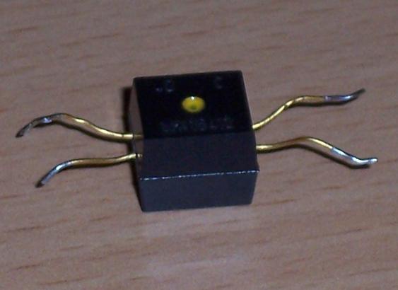
Optocouplers have different emitters (incandescent lamps, neon lamps, LEDs, light emitting capacitors) and different radiation sensors (photoresistors, photodiodes, phototransistors, photothyristors, porosimetry). They also differ in the Pinout. It is therefore necessary to find data on the type and Pinout of the coupler in either the reference or measurements, or in the scheme of the device where it was installed. Often deciphering the Pinout of the opto-coupler applied directly to the cost of this device.If the unit is modern, you can almost certainly be sure that the emitter is a led.
3
If the light receiver is a photodiode, it connect multimeter, to measure DC voltage to 200 millivolts. In all other cases, the receiving element of the optocoupler will turn on in the correct orientation, in a chain consisting of a DC voltage of a few volts, the resistor is calculated so that the current through the radiation detector is not exceeded, and multimeter, to measure current at the appropriate limit.
4
Now enter the emitter of the optocoupler to work. To turn of the led pass through it in straight polarity DC current equal to the rated. The incandescent lamp apply rated voltage. Neon lamp or light-emitting capacitor, taking care connect to the network through a resistor of 500 kω to 1 Mω and a capacity of at least 0.5 watts.
5
The detector must react to the inclusion of the emitter an abrupt change in regime. Now try multiple times to turn off and turn on the emitter. The photothyristor and the photoresistor will remain open and after removing the control action up to disconnect their supply. Other types of photodetectors will respond to each change of the control signal.If the optocoupler has an open optical channel, be sure to change the reaction of the radiation receiver due to the overlapping of this channel.
6
Making a conclusion about the state of the optocoupler, the experimental setup unplug and disassemble. Then solder the optocoupler back to charge or replace to another. We will continue repairing the device, which includes the optocoupler.