You will need
- - Arduino;
- - two-axis joystick;
- - 3 resistors of 220 Ohms;
- - 1 RGB or 3 regular LEDs.
Instruction
1
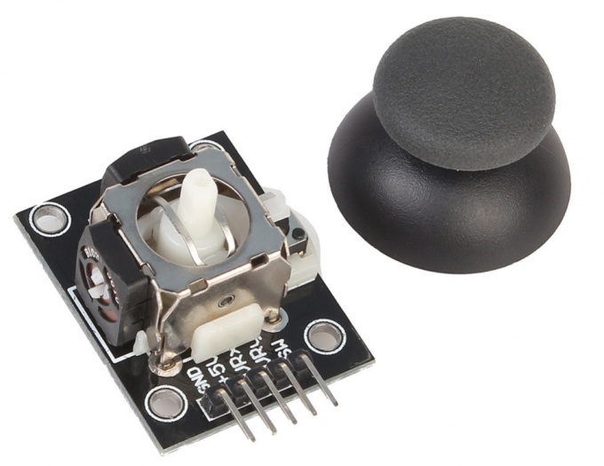
The joystick is easy and convenient to use device for the transmission of information. Types of joysticks in the number of degrees of freedom, the principle of reading and technology, there are many. Joysticks are often used to control the movement of any vehicles driven models of robots. Analog joystick, which we will discuss today is a handle attached to a ball joint with two mutually perpendicular axes. When you tilt the pen, the axis rotates the sliding contact of the potentiometer, thereby changing the voltage at its output. An analog joystick has a clock button which is triggered when the vertical pressure on the handle.
2
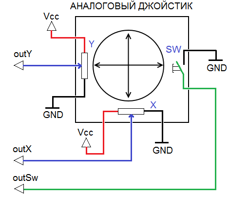
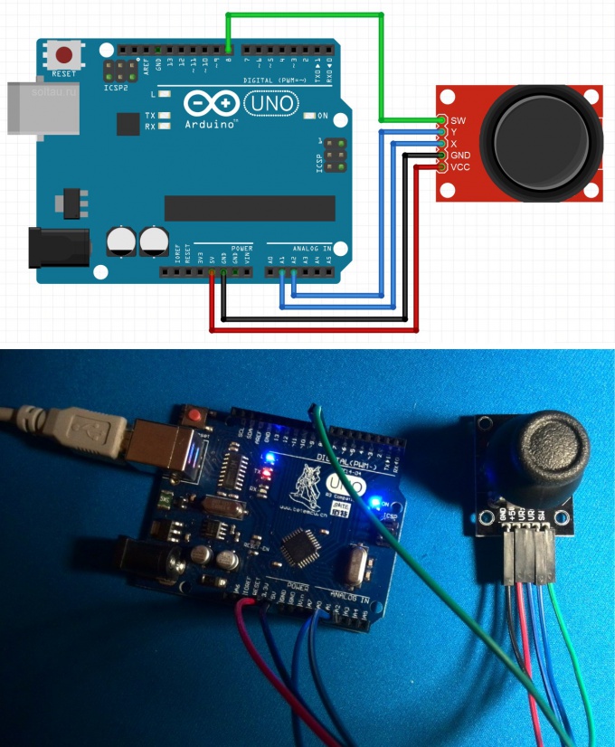
Connect the joystick via the following diagram. Analog outputs X and Y of the joystick connect to the analog inputs A1 and A2 of the Arduino, the output SW button to digital input 8. The power of the joystick is performed by the voltage of +5 V.
3
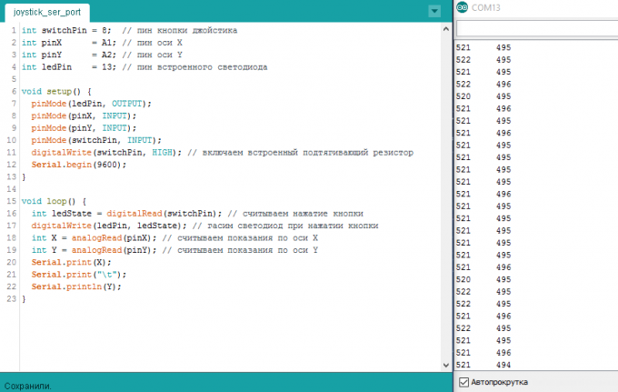
In order to clearly see how the joystick works, let's write a sketch. Declare the pins, let them have modes. Please note, in the procedure setup() we have filed at the input switchPin high level. We've included built-in pull-up resistor on this port. If not included, then when a joystick button is not pressed, the 8th port of the Arduino will hang in the air and catch the pickup. This will entail a chaotic unwanted false alarms.
In the procedure loop() we constantly interrogate the state of the button and display it via the led on output 13. Due to the fact that the entrance switchPin pulled up to the power supply, the led is always on, and when you click off, and not Vice versa.
Next, we read the testimony of the two potentiometers of the joystick output axes X and Y. the Arduino has 10 bit ADC, so the values are taken from the joystick, range from 0 to 1023. In the middle position of the joystick, as seen in the illustration, remove the values in the region of 500 - about the middle of the range.
4
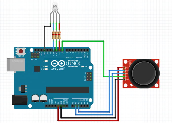
Usually a joystick is used to control the motors. But why not use it, for example, to control led brightness? Let's plug in the above scheme RGB led (or three ordinary LEDs) to digital ports 9, 10 and 11 of the Arduino, not forgetting, of course, about the resistors.
5
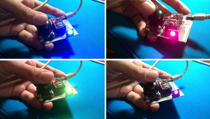
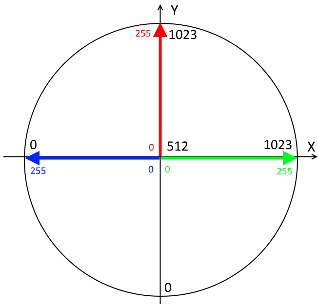
Will change the brightness of the corresponding colors by changing the position of the joystick on the axes, as shown in the figure. Due to the fact that the joystick may not be centered exactly to the manufacturer and have the middle of the scale not at the level of 512, and from 490 to 525, the led may be dimly lit even when the joystick is in the neutral position. If you want to he was completely off, then add the appropriate amendments.
6
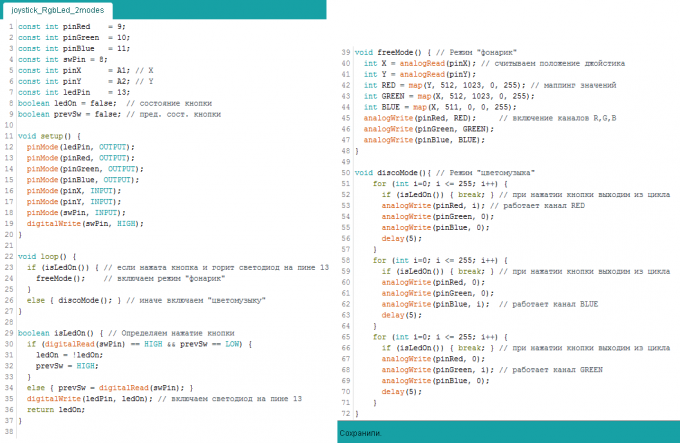
Focusing on the given diagram, write sketch Arduino control the brightness of the RGB LEDs with the joystick.
First, declare the conformity of pins and two variables - ledOn and prevSw - to work with the button. In the procedure setup() assign pins function and connect to pin button pull-up resistor command digitalWrite(swPin, HIGH).
In the loop loop() define button of the joystick. When you press the button to toggle the modes between "flashlight" mode and "sound to light".
Mode freeMode() to control brightness of LEDs by tilting the joystick in different directions: the greater the tilt axis, the hotter and brighter the color. Moreover, the transformation of values assumed by the function map(value, Otieno, overhage, book reviews, to the upper). The map() function takes the measured values (Otieno, overhage) according to the axes of the joystick in the desired range of brightness (book reviews, to the upper). It is possible to do the same ordinary arithmetic, but this entry is much shorter.
Mode discoMode() three colors alternately gaining brightness and off. To be able to exit the loop when the button is clicked, each iteration check whether the button is pressed.
7
The result is a flashlight of three-color RGB LEDs, the brightness of each color which is set by using the joystick. And when you click on button you activate the "colour music". Although I have used it, on the contrary, as a nightlight.
Thus, we learned how to connect to Arduino analog two-axis joystick with a button and read his statement. You can come up with and implement a more interesting use of the joystick, than our example.
Thus, we learned how to connect to Arduino analog two-axis joystick with a button and read his statement. You can come up with and implement a more interesting use of the joystick, than our example.