You will need
- - parts from an old tube radio or TV;
- - soldering iron;
- accessories for soldering;
- - aluminium sheet.
Instruction
1
Make of aluminium sheet chassis, U-shaped according to the dimensions of your existing parts. Provide its vertical front panel from aluminium. It will be possible to place the controls. The power supply is take from the radio, television, gramophone, etc. Must be given a constant anode voltage 150-250V, and the filament voltage of 6.3 V.
2
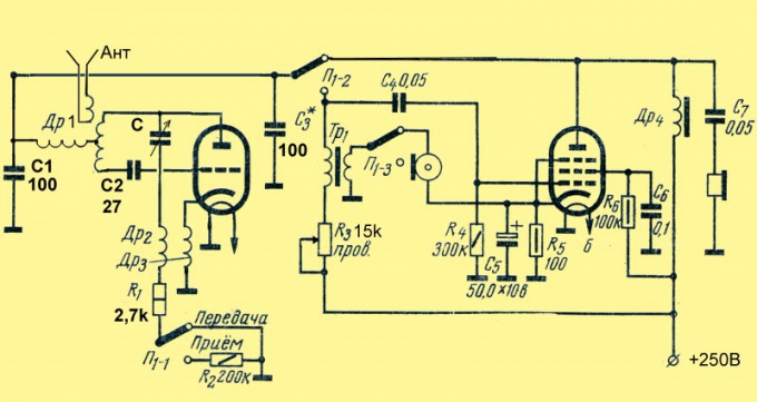
Collect the radio for the transceiver circuit, as shown in the figure. Coil loop transceiver is copper wire with a diameter of 1 mm. Wire take naked, and even better - silvered. For the range of 27-30 MHz it is wound on the rod 12 mm in diameter, and contains 4 turns with a tap in the middle.
3
Coil connection antenna contains 1 to 2 turns of the same wire and is on top of the coil circuit. Chokes DR1, Др2 and Др3 wrap the resistance of VS-0,25 resistance not lower than 1 mω. They contain 0.5 m of wire PEL-0,15.
4
The condenser settings With you can take the ceramic 4-15 pF (trimmer), but it's better if it will be with an air dielectric with one movable and two fixed plates. If you are going to work only on one particular channel, the tuning knob to supply is not required.
5
TP1 transformer (audio transformer TVZ or similar output tube) take the tube from the receiver or TV. High resistance winding of the same transformer used as a choke Др6. If you want to use low-resistance headphones, turn them in nizkoomnyj winding of the transformer. The following diagram shows the inclusion of high impedance phones.
6
Microphone use coal. For example, from the telephone. The switch "Reception - Transmission" approach, the app switches. They can be replaced by any other 3 of the contact group and 2 positions.
7
Configure the radio. Do the setting in reception mode. The variable resistor R3 until multi-stable noise at all positions of the capacitor settings. If you cannot achieve this, pick up the capacitance of the capacitor C3 in the range from 100 to 1000 pF. The setting range is carried out by the condenser, as well as pinching and spreading the coils of the loop coil. When the frequency settings carrier signal multi noise in the phones must be completely turned off. When you switch on the transmission to control the radio needs to be clearly heard the sound from the microphone.
8
The position of the coil connection antenna pick up so that the power PI of the transmission was maximum, and the reception is stable. As a control receiver and transmitter, you can use a pre-configured pocket radio.
Note
Keep in mind that the radio is designed for amplitude modulation and in conjunction with the FM radio will not work.
The diagram shows the connection of dipole antenna. But you can connect and pin. For this purpose one end of the coil connects to the chassis, and the connection to the antenna is through a coaxial cable (e.g., RK-1).
In the scheme used lamp 6Ф1П. But it is possible to collect a radio and a double triode (for example, 6Н1П or 6Н3П). The chain C6-R6 from the circuit is excluded. You can collect the radio and on two separate lamps, used as a triode half of the lamp 6Н7 or 6Н8, and as pentod - 6Ж4 or 6Ж8.