Instruction
1
On the wiring diagram the resistor are given without specifying the unit of measurement is generally expressed in ohms. For example, the number 200 means 200 Ohms. If after the numbers located lowercase letter K, we are talking about Kromah: 250 to 250 is file com. If the old schemes unit of measurement in the designation is absent, and the number in addition to a part is and the fractional, the value is expressed in megohms: 10,0 stands for 10 MW. On new schemes to do this, use the capital letter M: 5 M means 5 Mω. Capital letter G replaces the unit dimension D (gigaom). These resistors are rare, mainly in radiation equipment based on ionization chambers.
2
On the resistors instead of using the name Om unit uses either the Latin capital letter R or a capital Greek letter Ω (omega"). Kilome are denoted by the capital letter K, megohms - capital letter M, higami - uppercase Russian letter G Latin or G. the Numbers located before and after the letters is the equivalent of digits after the decimal point. For example, 2R5 - 2.5 Ohm, 120K - 120 ohms, 4М7 - 4.7 Mω. Less the resistance value is specified using the conventional notation of units, for example, 10 kω.
3
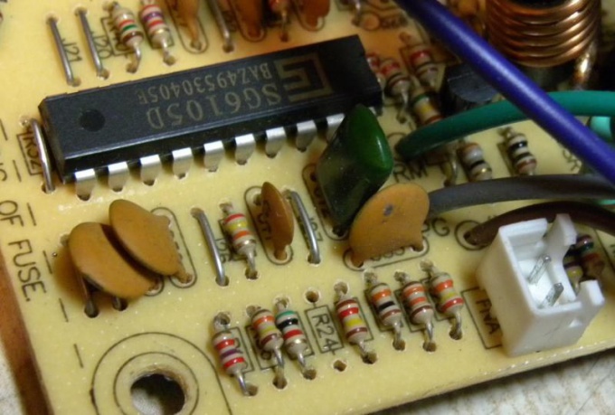
Using the color rings on the resistors are coded with different numbers. The following colors are used: black - 0, brown - 1, red - 2, orange - 3, yellow - 4, green - 5, blue - 6, violet - 7, grey - 8, white - 9. These bands may be three or four. All of them, except the last, represent numbers, and the last is number of zeros following those digits. The resulting number expresses the resistance in ohms, which can be converted to more convenient units.
4
If after them after a short period of located gold band, the resistor has a tolerance of 5%. The silver band tells about the tolerance of 10%, and if it does not exist, the tolerance on resistance equal to 20%. Countdown guide strips on the side opposite the strip, symbolizing tolerance.
5
The resistor on which the marking is absent, the resistance can be measured. To do this, power off the circuit, discharge the capacitors, confirm with a voltmeter that they are really discharged, and then desolder one lead of the resistor and connect it to an ohmmeter. Select the limit at which resistance is displayed most accurately. After reading the readings, disconnect the ohmmeter and solder the disconnected output back.