You will need
- - A set of keys;
- - screwdriver;
- - soldering iron 100W;
- - a multimeter or ohmmeter.
Instruction
1
For Troubleshooting remove the generator from the machine. Depending on the brand of machine and model of the engine, its location can be different, in some cases greatly complicates the procedure of dismantling alternator. To remove the alternator, loosen the hinged bolts, then loosen the belt tension with a key, turning in the adjustment bolt tension the generator belt until when you will be able to remove the belt from pulleys. If you are not going to change the alternator belt, remove the belt just from the alternator pulley, if the other belts prevent to remove it from the pulley. After removing the belt, disconnect the connector with the control wires and remove the nut which dragged the power lead to the terminal of the diode bridge of the generator. Releasing the generator, remove the fully hinged bolt and remove the mounting bolt connecting the body of the generator breaker. After that, remove the alternator from the engine compartment.
2
Disassemble the generator. To do this, use socket wrench remove the bolts holding the front and rear of the alternator, then carefully disconnect housing. Try to keep when disassembling the housing, the stator remains on the front wall, since the stator winding is directly soldered to the diode bridge.
3
Remove the diode bridge from the front wall of the generator. Using a Phillips screwdriver, loosen the mounting bolts of the diode bridge, then use the Allen key Unscrew the retaining nut from the positive terminal on the alternator. Look closely, perhaps negative terminal of the bridge also is secured to the body by a separate nut. If so, loosen this nut. After you Unscrew all the mounting bolts, remove the front wall of the generator.
4
Desolder the diode bridge from the windings of the generator. Preheat a powerful soldering iron, solder its tip, after which you will be able to easily unsolder the leads of the windings of the stator from the bridge. Otpaivala the terminals of the windings, slowly, applying the heated soldering tip to the soldering spot and at the time of melting the solder, using a flat screwdriver, as capture the insights of the bridge from the terminals of the windings. Desolder all 4 points, then the diode bridge will be released and it will ring.
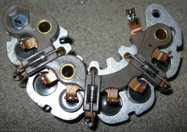
5
Using an ohmmeter, check each diode individually without dismantling the construction of the bridge, as the other diodes, if they are OK, do not affect the measuring result. The diodes should show conductivity only in one direction. If you have a DMM, pay attention to the readings. They should be close. This device shows not only the conductivity but also the voltage drop across switching diode. Normal voltage drop is 170-250 mV and depends on the specific brand of diodes. In the opposite direction, no conductivity should not be.