You will need
- The tester, permitting resistance measurement in the range of 100-1000 ohms.
Instruction
1
Prepare a diode bridge to check. Disconnect one of the connections of the diodes together. If the connections are made by soldering, desolder two diodes in place of their connection. It is necessary to exclude the influence of complex faults (breakdown of several diodes) on the test results. If the diode bridge is configured as an integrated Assembly, and preparation for verification is not required.
2
Prepare tester to work. Switch the mode to resistance measurement with a maximum value of 1000 ohms. Test the tester, the circuit closing contacts of the probes. The displayed resistance should be equal to zero.
3
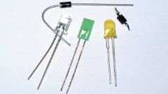
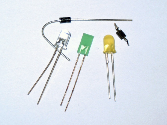
Test the diodes. Measure the resistance of each diode separately in two directions. Connect the probe of the tester to the pins of the diode. Read the resistance value. Adjust the probes swapped. Again, remove the statement. A healthy diode should have a resistance of several hundred ohms in one direction (depends on the semiconductor material - silicon or germanium) and an infinite resistance in the other. If the diode has a low resistance when measured in both directions, then the diode is broken circuit. If in both directions the diode has infinite resistance, then the diode is broken open. Diode bridges in the form of assemblies are checked similarly. Verifiers from the breakdown of several diodes, able-bodied diode can be identified as faulty. But it doesn't change anything, since you have to replace the entire Assembly.
Note
Avoid testing diodes with connection using these bulbs. The current going through the diode may exceed the maximum allowed value for the diodes in this series and he will be out of action.
Useful advice
You can do a quick check of the diode bridge for malfunction by measuring the resistance in two directions between its outputs. The bridge needs to pass a current in one direction and not to miss in the other. Not the fulfillment of this condition indicates a faulty diode bridge. Implementation, however, does not mean that the bridge is serviceable.