Instruction
1
When reading the drawing view on the frame with which it is decorated. In the main writing frame, locate the name of the part or Assembly unit, her room and the material from which it is made (if item). In the case of the image on the drawing Assembly, you will see in column "Name" of the sheet the line that says "Assembly drawing".
2
Please note the image scale, which must be specified in the title block of the drawing. It shows how many times the image in the drawing are reduced or enlarged relative to the real object. The design uses the magnitude of the increase (e.g., 2:1, 4:1), which shows that the image in the drawing is increased in comparison with the real object. The scale of reduction (for example, 1:2, 1:10), in turn, showing how the image in the drawing is reduced compared to the object.
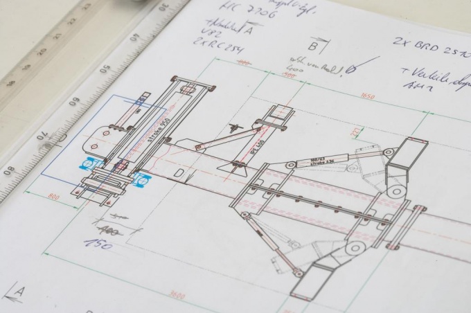
3
Find the main view of the depicted object. Most likely, it will suffer the largest number of dimensions (including dimensions). Carefully consider this view. Pay attention to the cuts and sections, if any, as they give an insight into the inner shape of the part. The area of a part or Assembly that falls in the plane of the section or sections in the drawings is depicted as hatched. Some sections and sections are made separately, they are designated by capital letters with a hyphen (e.g. a-A,-B).
4
For a more accurate representation of an object use other types shown in Fig. Most likely it will be the left side view and top view. Additional types are denoted by capital letters (e.g., D or G).
5
Note the stated sizes. Usually they are specified with tolerances, which describe the precision manufacturing of a part or Assembly units. The detail drawing should also be applied to indicate the roughness of the surfaces.
6
Read the technical requirements. This is the text located above the title block of the drawing. It carries information about the manufacture, storage and operation of the facility.
7
Process documentation to include itinerary and operating card. When reading the route maps note the General requirements of the part or Assembly. Next you will see the sequence of operations necessary for manufacture of an object. The numbers before the name of the operation characterize the number of workshop, workplace and room the operation itself. Then lists a sequence of actions, and at the end of the transaction, you specify the applied tools and accessories.
8
Operating the map you will find a description of one operation and specific guidance for the processing of a part or Assembly units. In the map must be specified standard time, the necessary fixtures and tools, modes of production, as well as drawn sketches of installation details or host device.
9
Look on the first page of technical documents or in the title block of the drawing the name of the developer, and if you have any questions regarding the design or technological documentation, contact them.