You will need
- - A set with a digital oscilloscope DSO138;
- - multimeter;
- - power supply 8-12 V;
- - tweezers;
- - screwdriver for small jobs;
- - soldering iron;
- - solder and flux;
- - acetone or gasoline.
Instruction
1
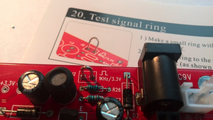
First, solder a loop of wire of thickness 0.5 mm in the hole of the connector J2. It will be a contact signal output self-test of the oscilloscope.
After this short-circuit using a soldering iron and solder the contacts of the jumper JP3.
After this short-circuit using a soldering iron and solder the contacts of the jumper JP3.
2
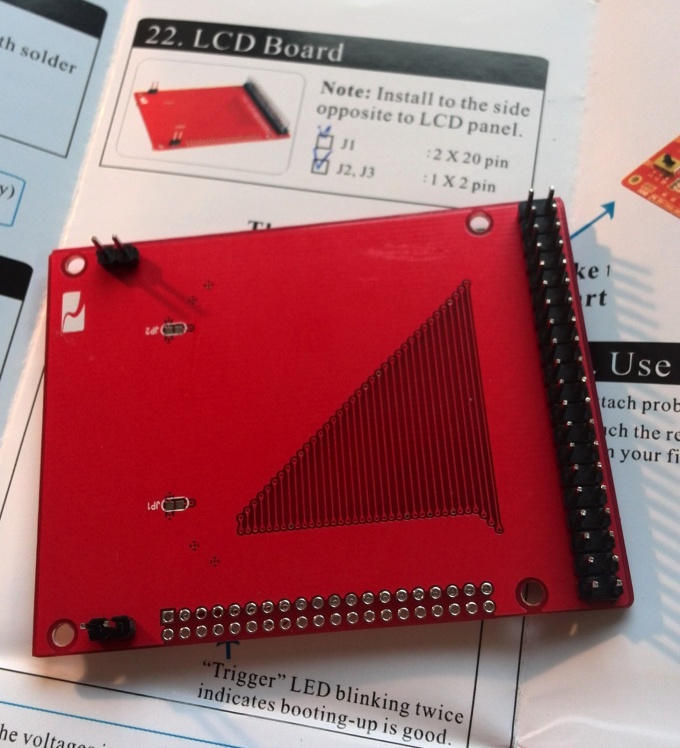
Make cost TFT LCD screen. Need to solder the 3 pin connector on the bottom of the Board. Two small connector on the two pins single and double row 40-pin.
We are almost finished with the Assembly. But do not rush to remove the soldering iron, we'll need it.
We are almost finished with the Assembly. But do not rush to remove the soldering iron, we'll need it.
3
Now it is advisable to clean the Board with acetone, gasoline or any other way to clean traces of flux. When wash cost, you need to give it to dry thoroughly is very important!
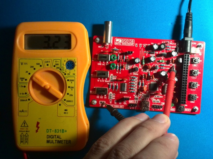
Then connect the power supply to the Board and measure the voltage between ground and point TP22. If the voltage is approximately equal to 3.3 volts, so you are all well soldered, congratulations! Now you need to disconnect the power source and short circuiting the contacts solder jumper JP4.
Then connect the power supply to the Board and measure the voltage between ground and point TP22. If the voltage is approximately equal to 3.3 volts, so you are all well soldered, congratulations! Now you need to disconnect the power source and short circuiting the contacts solder jumper JP4.
4
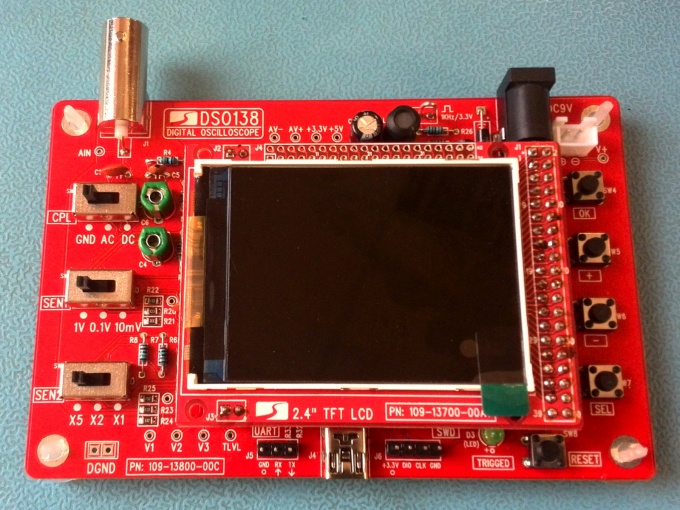
Now you can connect to the oscilloscope LCD display, lining up the pin type leads with the pads on the circuit Board of the oscilloscope.
Connect the power supply to the oscilloscope. Should turn on the display twice to blink the led. Then a couple of seconds the screen will display the logo of the manufacturer and boot information. After that, the oscilloscope will enter into working mode.
Connect the power supply to the oscilloscope. Should turn on the display twice to blink the led. Then a couple of seconds the screen will display the logo of the manufacturer and boot information. After that, the oscilloscope will enter into working mode.
5
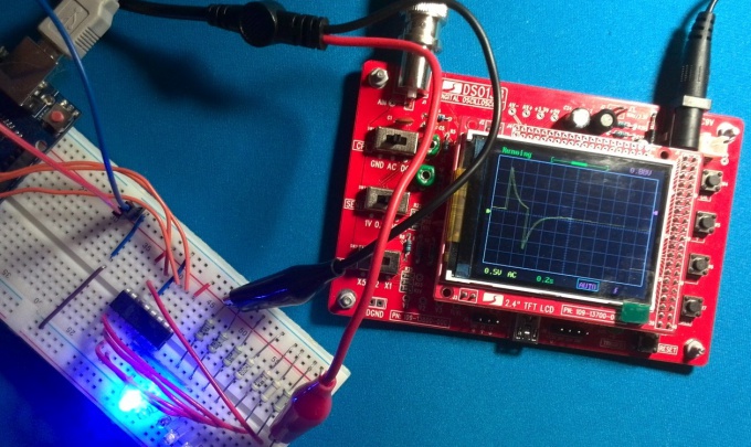
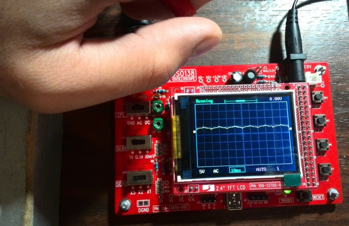
Connect the probe to the BNC connector on the oscilloscope and draw the first test. Will not connecting the black wire probe, touch the hand to red. The waveform should appear signal interference from your hand.
6
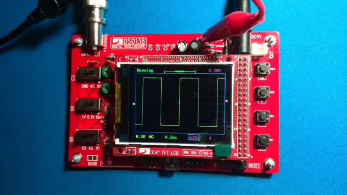
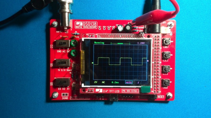
Now otkalibrovani oscilloscope. Connect the red test lead probe to the loop signal self-test, and leave black unconnected. Switch SEN1 put in the position of "0.1 V", SEN2 to "X5", and CPL is in position "AC" or "DC". Using the clock button SEL to move the cursor to the time stamp, and the buttons "+" and "-" set time "0.2 ms", as in the illustration. On the waveform should be a nice square wave. If the edges of the pulses are rounded or have sharp peaks at the edges that need turning with a screwdriver the capacitor C4, to ensure that the signal pulses have become as close as possible to rectangular.
7
Now switch SEN1 put in position "1V", SEN2 - to "X1". The rest of the settings will keep. Similar to the previous paragraph, if the waveform is far from rectangular, you will fine-tune it by adjusting the condenser C6.
8
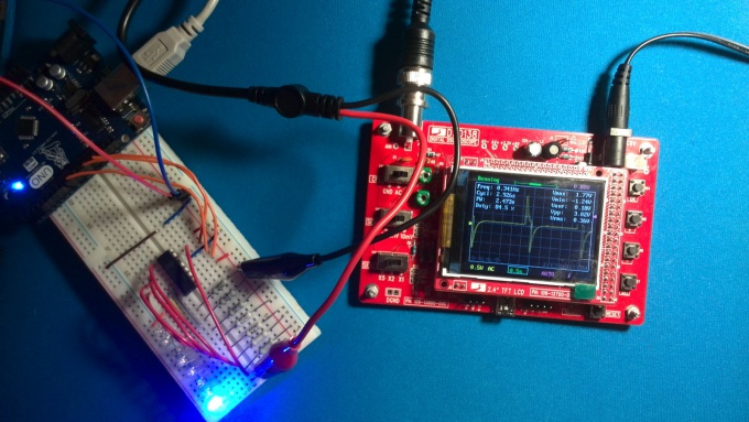
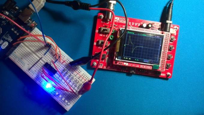
In this setting the oscilloscope DSO138 over. Let's test it in combat conditions.
Connect the probes of the oscilloscope to an electrical circuit and view the signal.
Connect the probes of the oscilloscope to an electrical circuit and view the signal.
9
Sensitivity can be controlled are the switches SEL1 and SEL2. The first of these sets the base voltage level, the second the multiplier. For example, if you put the switches in position "0.1 V" and "X5", resolution of the vertical scale will be 0.5 volts per cell.
Button SEL to move around screen elements that you can configure. Setting the selected item is carried out with buttons + and -. Items to configure are: sweep time, trigger mode, select the front trigger, trigger level, movement along the horizontal axis of the waveform, the moving axis vertically.
Supported modes: auto, normal and single. Auto mode continuously outputs the waveform on the oscilloscope screen. In normal mode, the signal is output every time when it exceeded a preset trigger threshold. Single mode outputs the waveform during the first trigger.
The button OK allows to stop the scan and hold current waveform on screen.
The button RESET resets and restarts the digital oscilloscope.
A useful feature of the oscilloscope DSO138 - display information about the signal: frequency, period, duty cycle, magnitude, medium voltage, etc. to activate it, press and hold the button for 2 seconds OK.
The oscilloscope is able to remember the current waveform in nonvolatile memory. To do this, simultaneously press the SEL and +. To display stored in the memory of the waveform, press the SEL and -.