You will need
- pencil;
- - the range;
- a pair of compasses;
- - a triangle.
Instruction
1
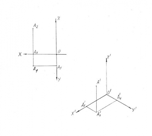
When designing on a plane axonometric projections N’ natural coordinate system Oxyz will axonometric coordinate system O ' x'y'z’, and the projection of any point of the axonometric projection or axonometric view A’ (figure 1). If you move from plot the horizontal projection of point A₁ of the new system, it will be so-called secondary projection and the point will have the axonometric coordinates.
2
The ratio of the axonometric coordinate is called the natural rates of distortion on the axes. They are designated u, v, w, and the magnitude of the angles between the axonometric axes respectively, α, β, and γ.
There are different types of perspective. In an engineering drawing often used rectangular and axonometric. Depending on the values of the distortion u, v, w rectangular axonometric view is divided into types:
- isometric – indicators of distortions in all three axes are equal u=v=w.
the diameter of the indicators of distortion are equal in two axes u=w≠v.
Typically, the metrics of distortion u, v, w have fractional values, but to simplify the build using the given values. For example, in the isometric view given coordinates equal natural.
3
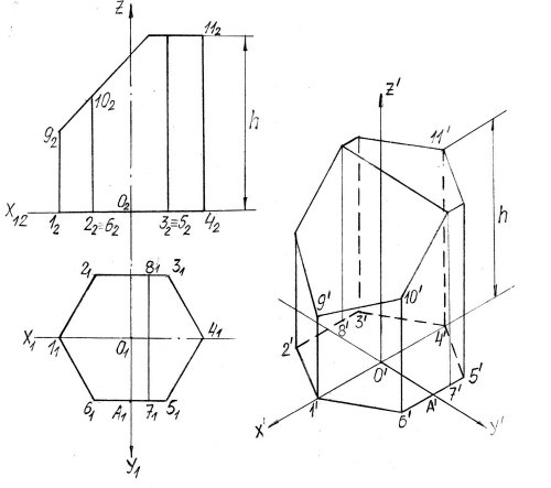
Example. To build a rectangular isometric projection of the prism (figure 2).
Complex drawing of a prism is specified in the system of axes xyz, the origin point O.
Complex drawing of a prism is specified in the system of axes xyz, the origin point O.
4
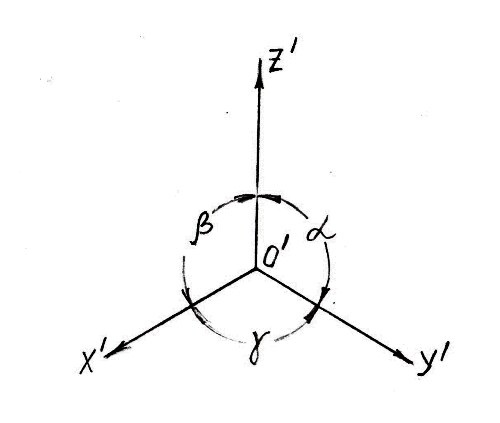
Construct axonometric axis O x'y'z’. The angles between the axes α, β, γ is equal to 120⁰ (figure 3).
5
In the axonometric axes build a secondary projection of the prism. Let the origin point O’ and the axis z’ passes through the major axis of the prism z. All sizes with comprehensive drawing, move on the axis x O y’ unchanged because the coefficients of distortion on the axes equal to 1.
From the point O’ put cut and О₁1₁ О₁4₁ axis x’. Mark the points 1’ and O’, and y’ put cut OA. Get the point O’, A’.
From the point O’ put cut and О₁1₁ О₁4₁ axis x’. Mark the points 1’ and O’, and y’ put cut OA. Get the point O’, A’.
6
On the plot cut 6₁5₁ parallel to the axis x₁, hence, the segment 6’5’ guide parallel to the axis x’. Put it distance А₁6₁ and А₁5₁. Mark the resulting point 6’, 5’, and similarly to construct symmetric points on the 2’, 3’.
7
Determine the position of the points 7’ and 8’, putting aside the size 7₁А₁. Thus, in axonometric projection is constructed of a secondary projection of the base of the prism– 1’,2’,...8’. From each point draw straight, parallel to the axis Z’. On these lines set the height of each point with the frontal projection of the prism on the plot.
From point 1’ put cut 1₂9₂, and from the points 2’ and 6’ – cut 2₂10₂. From the rest of the points 3’, 4’, etc. set aside marked with the height h. Combining all constructed points will get a perspective of the prism.
From point 1’ put cut 1₂9₂, and from the points 2’ and 6’ – cut 2₂10₂. From the rest of the points 3’, 4’, etc. set aside marked with the height h. Combining all constructed points will get a perspective of the prism.