Instruction
1
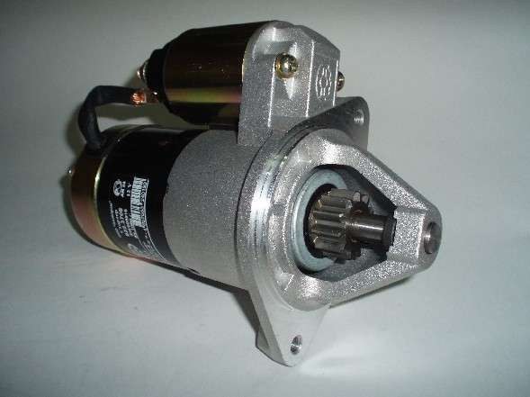
Install the starter on the bench. Test its electrical and mechanical characteristics. Note, however, that the connecting leads from the power source to the ammeter and the contact bolt of the traction relay should be a cross section of 16 sq. mm. Starter connect a fully charged battery. The temperature during testing shall be (25±5) degrees. Brushes should be well lapped on to the manifold.
2
Check the operability of the device. Install source voltage 12V, the circuit between the "+" battery terminal 50 on the starter , check the switch. Closing it produces four enable starter with different conditions of braking: 2-2,4; 5,5-6,6; 9-10,8 and 11.5 to 12.5 Nm. The duration of each inclusion of a starter should not exceed 5 seconds, an interval between them of from 5 seconds. If the job starter is accompanied by abnormal noise or rotates the ring gear, it should be disassembled and check the details.
3
Test the starter in the full braking. This fully secure motionless ring gear of the stand, crank the engine and measure the current, torque and voltage, which should correspond to values not higher than 500 And not less than 14 Nm and do not exceed 6.5 V. the Duration of the process of inclusion should not exceed 5 seconds. In the case where the braking torque below the required figure, but the amperage is higher, then the cause could be shorting the windings to ground or a winding short circuit in the armature winding and the stator. If the brake time and current are below the standard values, it can be caused by pollution and oxidation of the collector, reducing the elasticity of springs of brushes or severe deterioration, excessive wear of the brushes stuck in the brush holders or loose conclusions of the stator winding, the burning or oxidation of the contact bolts of the traction relay of a starter.
4
Check the traction relay. To do this, set between the gear and the restrictive ring gasket with a thickness of 12.8 mm. plug relay. Power consumption-DC single relay should be no more than 23 A. Check the switching voltage at the two-winding relay. It should be no more than 9 V. If it is higher, then a faulty relay or an actuator.