Instruction
1
Based on the graphic part of the planand the evacuation take the floor plan of the building. Note that, if floor area more than 1000 sq m, it is necessary to break it down section and for each of them to draw a separate diagram. If a floor plan is available only in paper form, then scan it and use the bitmap as a sub-base for the design planand evacuation in electronic form.
2
Go around all the premises located on the floor, inspect them. Mark on the plan, e the location of phones, fire extinguishers, automatic fire alarm, fire hydrants, main, spare and emergency exits. For each room specify the number of people in it and the estimated average number of visitors, if they rely uponthe presence in the room.
3
Inspect and verify all the basic, spare and emergency exits for their size and reliability. Note the presence of anisodamine and the possibility of ventilation.
4
Will watertite plan of the premises in any graphics program. Note the estimated size of a paper copy. For floor and sectional plans evacuation it must be at least 600x400 mm so it was a good read, andif youwere raised by visual. Local plan of evacuation from a separate room may be the size 400х300 mm.
5
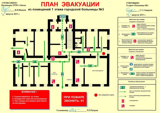
Consider options for ways out of each room taking into account the flow of people, sizes of the communication paths. Keep in mind, and those threads that can be formed on upper floors. Check with a solid green arrows recommended basic ways of an exit from the floor for each room. Alternate routes of evacuation , draw a dotted green arrow.
6
In the diagram apply conventional signs the location of telephones, fire hydrants, fire extinguishing means and systems of fire automatics. Enter places of the main, spare and emergency exits. Be sure to indicate location on plane, which corresponds to the location of the scheme. On your drawing should have no unnecessary cluttering of details, decals, signs. A list of conventional signs must be whenadministered under the graphic.
Note
The height of signs and symbols must be 8-15 mm, they should be well readable and have the same size for the entire document. Safety signs and symbols can be colored, all the other graphic details and information appear in black.