You will need
- Voltmeter.
Instruction
1
Before performing this test make sure that the spark at the Central wire of the coil is indeed missing. After that, disconnect the connector that is connected to the switch. Connect the measuring device to the 1 and 2 terminals of the pads, then insert the key and turn the ignition on. Look closely at the voltmeter: it should show the value, which is equal to the voltage at the battery.
2
If the value does not correspond to what you expect to see, check the integrity of the wire that fits to the coil from the switch ignition. If necessary, replace damaged components. After that, connect to 2 and 4 connector on the block. Again turn the ignition on and look at the scale of the instrument. Voltage, which shows the tester should match the battery voltage.
3
Otherwise, disconnect wires from the battery, disconnect the switch connector and measure the resistance between "plus" of the battery 4 and the output of the switch, and between it and terminal 3. Fold the received data, as a result, you'll need to get a resistance value equal to 0.2 Ohms. Remember that these measurements should be carried out when the ignition is on.
4
After that bridge between the connectors that connect to the Hall sensor and switch. Connect the voltmeter to 3 and 5, the pins of the switch. Here, the readings should be 1 to 4 Volts less than the voltage level on the battery.
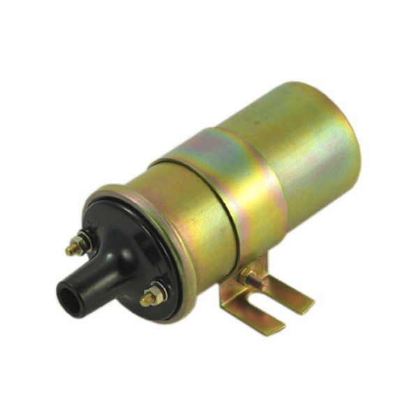
5
Inspect the coil and verify that the tube in the upper part is in its place. Then measure the resistance of the primary winding, which should be in the range of 0.6 to 0.9 Ohms. The same procedure repeat with the secondary circuit. Here, resistance values range from 6 to 9 kω.