You will need
- - strong thread;
- - adjustment ring;
- - torque wrench;
- - fine sandpaper;.
- - Vernier caliper.
Instruction
1
The reducer shall be subject to adjustment in the case that at speeds over 30 km/h audible hum. The reason for device failure can be the long-term operation of the machine in difficult conditions, e.g. repetitive strain or drive with a trailer.
2
Start repair-gearbox inspection. To do this, clean all parts with a brush and wash them in kerosene. Upon identifying any defects (damage to gear teeth) be sure to change the damaged part.
3
Pay attention to the edge between the top teeth and the working surface: they must be sharp. If there are curves or nicks, replace the main couple. Small defects can be polished with fine sandpaper, and then subjected to polishing.
4
When assembling the gear, put the new flange nut, collar and spacer. If you collect the device in the old Carter, calculate the change in size of the driving gear, its thumbwheel . So you learn the difference in the thickness deviation between the new and old gears. These designations are indicated by marks "-" and "+" in hundredths of millimeters on the shaft of the driving gear. So if the old gear is the number "10" and to a "-3", the difference will be 13: 3-(-10)=13. Thus, the thickness of the new adjusting rings must be less than the old 0.13 mm.
5
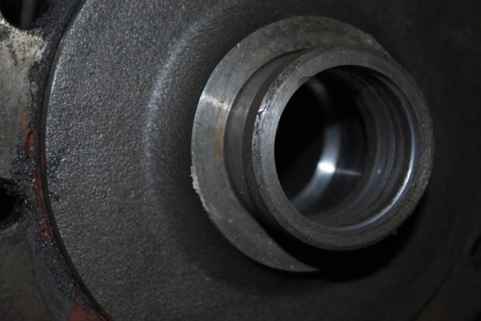
Fine sandpaper will clean under the bearings seat to the sliding position. Press into the crankcase bearing outer rings. With the help of a special device the inner ring of the rear bearing install into the crankcase. Further, the flange of the driving gear and the inner ring of the front bearing, tighten nut using a torque of 0.8–1.0 kgf.m
6
Using a level, put the crankcase in a horizontal position. To determine the amount of clearance between the fixture plate and a round rod mounted in the bed of the bearings, use a flat feeler gauge. The difference between the variance of the new gear and the gap indicates the thickness of the adjusting ring.
7
A section of pipe used as a mandrel, set on the shaft of the adjusting ring. Put the shaft into the crankcase. Next, install the parts in the following order: spacer, inner ring of front bearing, collar and flange drive gear. A torque wrench, tighten the nut to 12 kgs.m.
8
On the neck of the flange is tightly tied strong thread, adding to it the dynamometer. This way, you'll determine the starting torque shaft drive gear. With new bearings the flange is rotated under the force ,6-9,5 kgs. Otherwise, hold on the nut. Remember that the tightening torque must not exceed 26 kg.m. If when turning the moment of force more than 9.5 kgs, disassemble reducer and replace the spacer.
9
In the differential case with bearings check the crankcase. On the bearing cap lock bolts. If the gears of the axles you find the axial end play, install the adjusting shims thicker. The side gears must be installed tightly, but at the same time to scroll by hand. To tighten the nuts, use a steel key with a thickness of 3 mm.
10
Adjust pre-tension of the bearings of the differential, and the gap in the main pair, eliminating the gaps in engagement and tightening the nut driven gear. To measure the distance between the lids, use a Vernier caliper. Screw the nut 2 until it stops. The gap between the lids must be greater than 0.1 mm When rotating the first nut adjust the backlash in the gearing (0,08-0,13 mm). With proper repair will be heard the sound of small teeth.
11
Tighten both nuts while controlling a hand the size of the gap in engagement. Tighten nuts until the distance between the caps will not exceed 0.2 mm. For 3 turns, turn the counter shaft, probing in engagement with the backlash of each pair of teeth. Install the retaining plate.