You will need
- - Arduino;
- - 1602 LCD display (16 characters, 2 lines);
- - I2C adapter FC-113;
- - connecting wires.
Instruction
1
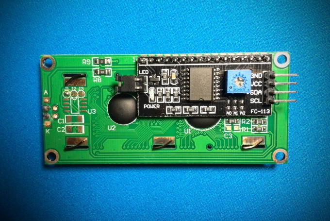
Module FC-113 is based on the PCF8574T chip, which is an 8-bit shift register - "extender" of the inputs / outputs for the I2C. Figure IC is designated DD1.
R1 is the trimming resistor for adjusting contrast of the LCD display.
Jumper J1 is used to enable the backlight.
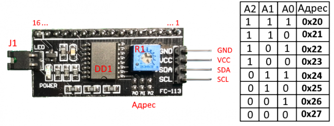
Insights 1...16 are used to connect the module to the conclusions of the LCD display.
Pads A1...A3 need to change the I2C address of the device. Sapaeva jumpers, you can change the address of the device. The following table lists the address mapping and jumper: "0" corresponds to the open circuit, "1" - installed jumper. By default, the device address 0x27, i.e. all 3 jumpers are open.
R1 is the trimming resistor for adjusting contrast of the LCD display.
Jumper J1 is used to enable the backlight.
Insights 1...16 are used to connect the module to the conclusions of the LCD display.
Pads A1...A3 need to change the I2C address of the device. Sapaeva jumpers, you can change the address of the device. The following table lists the address mapping and jumper: "0" corresponds to the open circuit, "1" - installed jumper. By default, the device address 0x27, i.e. all 3 jumpers are open.
2
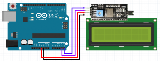
The module is connected to the Arduino is the standard for I2C bus: SDA output module connects to the analog port A4, SCL to analog port Arduino A5. The module is powered by the voltage of +5V from the Arduino. The module itself is connected between pins 1...16 with the respective pins 1...16 on the LCD display.
3
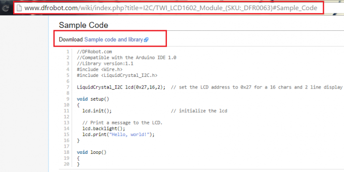
Now need a library to work with the LCD via I2C. It is possible to use, for example, like this: http://www.dfrobot.com/wiki/index.php?title=I2C/TWI_LCD1602_Module_(SKU:_DFR0063)#Sample_Code (link in the line "Download Sample code and library").
Downloaded archive "LiquidCrystal_I2Cv1-1.rar" rotaryforum in the folder "\libraries\", which is located in the directory of Arduino IDE.
The library supports a set of standard functions for LCD screens:
LiquidCrystal() - creates a variable of type LiquidCrystal and accepts the connection settings of the display (pin numbers),
begin() - initializes the LCD display, the setting of parameters (number of lines and characters);
clear() - clear screen and return cursor to start position;
home() - return the cursor to the initial position;
setCursor() - set the cursor to a predetermined position;
write() - displays the character on LCD screen;
print() - displays text on the LCD screen;
cursor() - shows the cursor, i.e. the underline under the next character;
noCursor() - hides the cursor.
blink() - blinking cursor.
noBlink() - cancels the flashing;
noDisplay() - turns off the display keeping all the display information;
display() - enable the display while maintaining all of the displayed information;
scrollDisplayLeft() - scrolls through display 1 position left.
scrollDisplayRight () to scroll contents of the display 1 position to the right;
autoscroll() - turns on Autoscroll;
noAutoscroll() - turns off auto scroll;
leftToRight() - sets the text direction from left to right;
rightToLeft() - text direction from right to left.
createChar() - creates a custom character for the LCD screen.
4
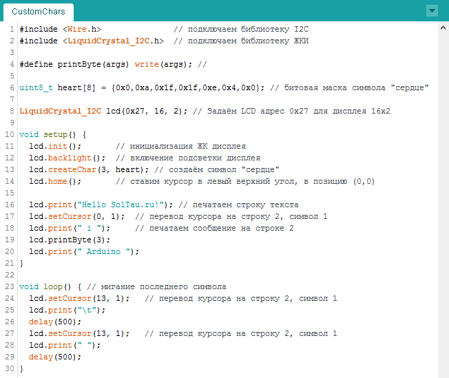
Open the example: File -> examples -> LiquidCrystal_I2C -> CustomChars and slightly Refine it. Print the message at the end of which will be a flashing symbol. In the code comments, commented out all the nuances of the sketch.
5
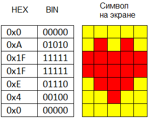
A little more, consider creating your own characters for LCD screens. Each character consists of 35 dots: 5 in width and 7 in height (+1 backup line to underline). In line 6 the above sketch, we set an array of 7 integers: {0x0,0xa,0x1f,0x1f,0xe,0x4,0x0}. Convert a 16-hexadecimal numbers in binary: {00000, 01010, 11111, 11111, 01110, 00100, 00000}. These numbers - not that other, as a bit mask for each of the 7 strings, where "0" denote the light point, and 1 is dark. For example, the heart symbol that is specified in the form of a bit mask will appear on the screen as shown in the figure.
6
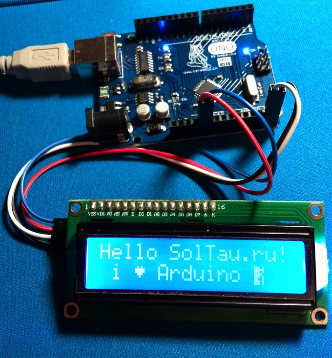
Upload the sketch in Arduino. Will appear on the screen for controlling the inscription with a blinking cursor at the end.