You will need
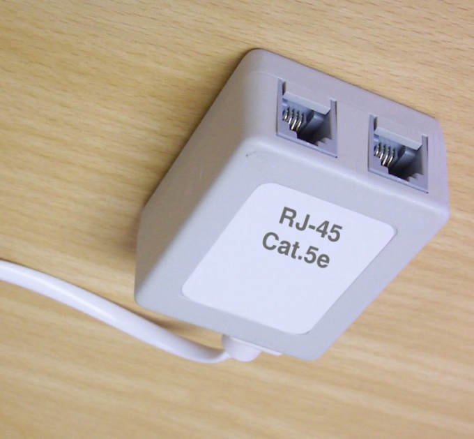
- socket Cat.5e;
- - screwdriver;
- cutters;
- - screws;
- - screwdriver.
Instruction
1
Cable which are to be connected to the socket attach to the wall whatever safe way (using staples or cable box). At the bottom of the socket locate the two latches. Click on them, and the cover is removable.
2
Thread the cable into the hole in the bottom, put in available from the opposite side of the channel, then using the screwdriver secure the base together with the connector and the terminal block on the wall with two screws. Be careful not to pierce the cable.
3
Remove the last outer shell to a length of about 2 see Themselves core strip to a length of about 0.5 cm (terminal block sockets unlike Ethernet plugs are not always equipped with automatic devices for piercing the insulation).
4
View, which scheme (A or B) is compressed Ethernet plug on the opposite side of the cable (where is the switch or router). If the plug has a sticker on the terminal block with two rows of colored squares, connect the wires according to the labeled 568A scheme A, or according to the 568B scheme B.
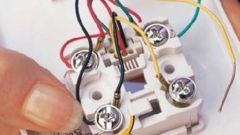
5
In the absence of the stickers, considering that the Foundation turned down terminal block, and the socket - up, connect the conductors in the direction from the left contact to the right in the following order: for option A - brown, brown-white, orange, orange-white, blue, blue-white, green, green-white, B - brown, brown-white, green, green-white, blue, blue-white, orange, orange-white.
6
Note that these wiring diagrams are different from those used in the crimping of the Ethernet plugs: the conductors on the terminal block for convenience, grouped by color pairs, and that in some designs outlet wiring diagram may differ from that described above. For example, it may be the same as on the plug, or contacts for blue and blue-white wires can be located to the right of the others.
7
If the terminal block is a double row, then, assuming that the outlet is directed upwards, and the terminal block is located underneath, often used this wiring diagram: left row, top to bottom, for schemes A and B: brown, brown-white, blue, blue-white, right row, top to bottom, for scheme A: green-white, green, orange-white, orange, right row, top to bottom, for the scheme B: orange-white, orange, green-white, green.
8
Close the socket cover, and connect it to the network card of the computer cable, compressed according to the direct circuit (in any case not according to the scheme of Crossover), then make sure you have a connection.