You will need
- - Arduino UNO or equivalent;
- - ultrasonic distance meter (ultrasonic module) HC-SR04 or similar;
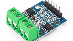
- - the motor driver L9110S or equivalent;
- - tracked platform for the tank Pololu Zumo or equivalent;
- a piece of fiberglass the size of the Board or Arduino shield for prototyping;
- - 2 motor, suitable to the selected chassis;
- - 2 white LEDs (front "lights"), 2 red LEDs (rear "lights") and 4 180-220 Ohm resistor;
- - batteries (1 "Crown" or penlight 4-6);
- - connecting wires;
- - soldering iron;
- computer;
- - fasteners - 6-10 bolts M2,5, washers, nuts to them.
Instruction
1
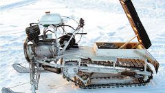
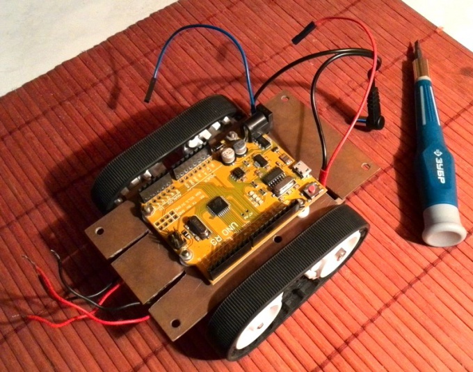
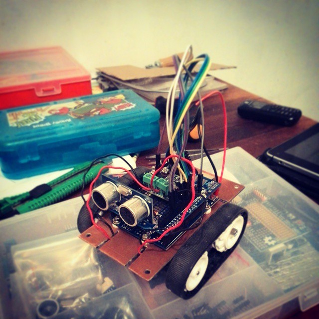
First, collect the platform. In a previous article we have discussed in detail how to make the chassis of the toy vehicle. Here the steps will be exactly the same. Why dwell on it will not. Collected the chassis for all-terrain vehicle with installed on them with an Arduino Board shown in the photo.
2
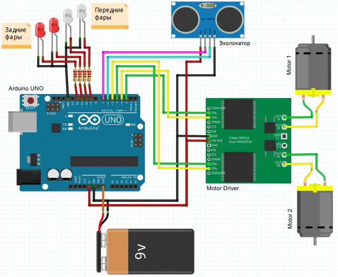
It is now the turn for electronics. First, consider the wiring diagram. Please note that all the LEDs are connected through resistors with a nominal value of about 200 Ohms. The sonar is connected to two arbitrary digital pins to the Arduino and +5V. Driver connection of the motors to the Arduino and to the motors shown in the diagram. If you have any uncertainty, read the previous article where we discussed this in more detail, or ask questions in the comments.
3
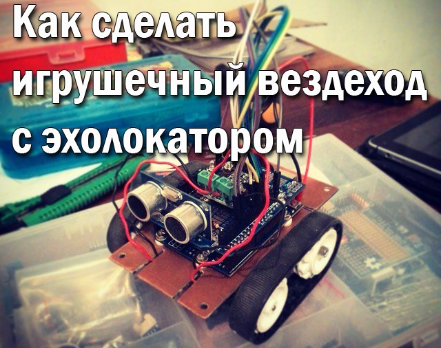
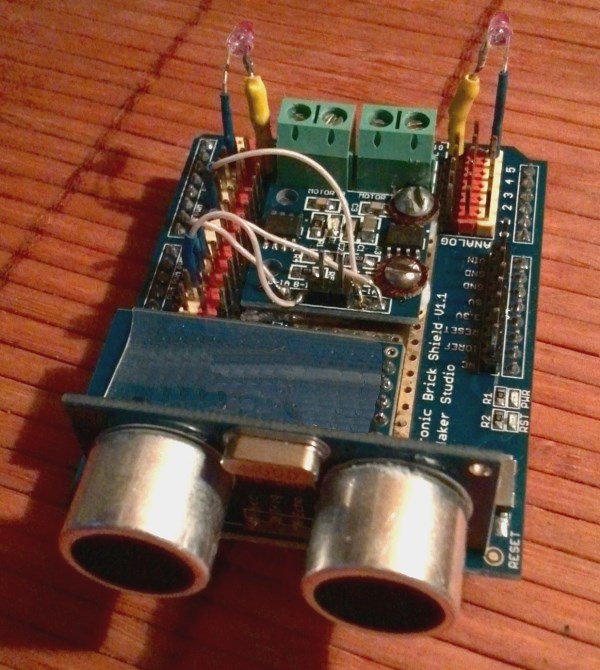
Gather on the diagram above, the heart and brain of our toy ATV. You can mount everything on a circuit Board is much easier for installation and possible future modifications. The photo electronic components are placed on a special Silde for prototyping for Arduino UNO. The sonar looks straight ahead movement of the vehicle. Rear LEDs will simulate the stop-signal lights, front, respectively - headlights.
4
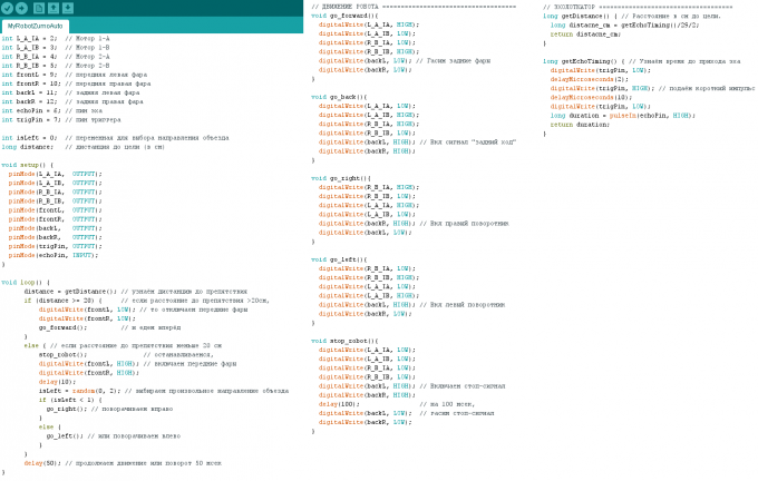
Time to write a program for the management of our vehicle. The code of the sketch (programs for Arduino) shown in the illustration.
The main caveat in this sketch to work with sonar. The point is that we send a short pulse trigger measure the delay time of the echo - reflection and time delay determined by the distance to the target. If the distance is less than the specified (in the sketch - 20 cm), the Rover inspects it.
The control algorithm of the engines we considered in the previous article. When you turn the Rover will include a "turn signal", when stopping - brake. When an obstacle is detected will be included headlights, and the Rover will drive around it. To the vehicle was more "intelligent", let us ask him a random direction around obstacles.
The comments in the code explain the whole program in more detail.
5
"Pour" a sketch in an Arduino (we have already discussed in past articles several options how to load a program with an Arduino). Connect the shield with electronic components of the Rover to the Board Arduino. The power supplied. And watch our the Rover "alive".
Useful advice
Order all the parts in the Chinese online stores. It will be 4 times cheaper than buying it in regular stores. But will have to wait, on average about 1 month.