You will need
- An ohmmeter, a device PDO-1
Instruction
1
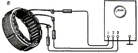
Check the winding of the rotor. To do this, turn on the ohmmeter to measure winding resistance and bring his findings to the rings of the rotor. Resistance serviceable rotor when voltage of 14 V is in the range of: generators that operate with voltage regulators designed for a maximum amperage of 3.5—4.0 And Is 3-5 Ohms, working with voltage regulators that are rated for the amperage And 5 - 2,5—3 Ohms.If the device showed infinite resistance, this means that the circuit of the field winding is broken. This usually occurs in the soldering of conclusions of a winding to the rings, when burned windings or when turning of the frame with the excitation winding on the pole half-sleeves-half. Also this is evidenced by the darkening and also shedding its isolation that can be detected visually. This fault leads to inter-turn short circuit in the winding, which is accompanied by a decrease in the overall resistance.To determine the partial winding short circuit when the resistance of the windings varies little, only a special device, such as PDO-1. When this occurs, the comparison of this coil with a known good. The excitation coil of the contactless generators (HA2, 955.3701) test using an ohmmeter, pin the ends of which are connected directly to the terminals of winding. Then check the no short to ground. To do this, one lead of the ohmmeter to bring his beak, and the other to any ring rotor, and the non — contact generators to the hub of the coil and any output coil. A good coil should show a gap on the ohmmeter, i.e. infinite ohms.
2
Check the stator winding. To do this, attach the ends of the ohmmeter to one terminal of the winding and package of iron, i.e., check for a short to ground. The device is a healthy coil should show an open circuit. Check winding short circuit in the stator windings. To do this, measure the resistance of the individual phases and compare the results with each other, the difference should not be more than 10%. The resistance phase is a fraction of an Ohm, so it requires high-precision measurement devices.Full information on the state of the windings of the generator can provide the device PDO-1, connected to the terminals of the three phases. When the phases are identical, the screen has one oscillographic curve, if not (due to inter-turn short circuit in phase) then the two curves. The measurement should be repeated, pre-change phase places. Thus you can find the different phases, for example, a different number of turns in them that can occur after rewinding the stator. Phase loss check with ohmmeter by connecting it alternately to the zero point and to the conclusion of each phase.