Instruction
1
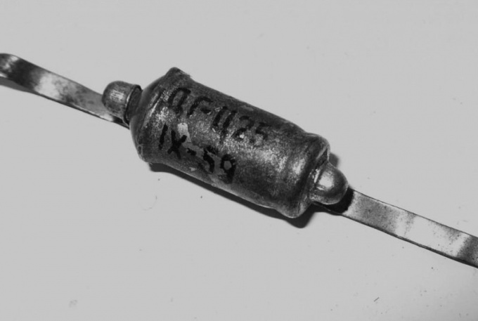
The cathode of the diode is the negative electrode, and the anode is positive. When the voltage applied to the diode in this polarity, its resistance becomes very small, and can be a considerable current; and when in reverse polarity, the resistance becomes very large, and the current is so small that it can be ignored. But note that the polarity of the output voltage of the rectifier depends on the electrode connected to the voltage source. The same load is attached to the opposite conclusion.
2
For example, if the output half-wave rectifier need to get a voltage that is positive relative to the common wire, connect the anode of the diode to the secondary winding of the transformer and the cathode to the load. The remaining unconnected insights, as winding, and the load must be connected to the common wire.
3
Full-wave rectifier will require for its manufacture of two diodes and a transformer with a tap from the middle of the secondary winding. Connect the outlet with the common wire and to each of the extreme terminals of the secondary winding connect the anode of the diode. The cathodes connect them together. The positive contact of the load connect to the connection point of the cathodes of the diodes, and negative — to the common wire. If you change the polarity turn on both diodes, then you have to change the polarity of the switching load.
4
The bridge rectifier consists of four diodes. Take two diodes and connect the anode of one of them to the cathode of the other, and the remaining conclusions yet will not connect. This will be the first point of supply of the AC voltage. Repeat with the remaining pair of diodes, and get a second feed point of the AC voltage. Connect the remaining cathodes, and you get the point of removal of the positive rectified voltage. Connect the remaining anodes, and get the point of removal of the negative rectified voltage. Bridge rectifier, possessing all the advantages of the conventional full-wave, does not require the presence of the secondary winding of the withdrawal.
5
If the load is sensitive to ripple, connect parallel to it, the polarity of the filter capacitor. Note that this output voltage will increase (to 1.41 times). Do not exceed the following parameters of the diode: maximum load current (i.e., maximum current that can flow through the diode when it is open) and the maximum reverse voltage (i.e., voltage applied to the diode when it is closed). Do not touch the conclusions of parts under high voltage (there may exist in the secondary circuits), and circuits not isolated from the network - do any parts. When filters, before touching the parts after de-energization discharges the capacitor.


