You will need
- - a sheet of paper;
- - 2 projection of components;
- - drawing tools.
Instruction
1
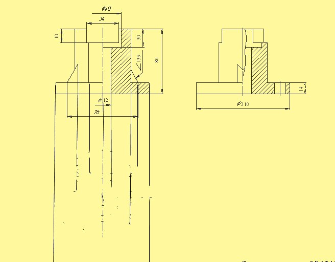
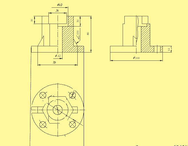
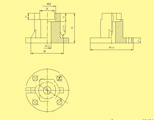
The principles of the third type are the same for classic drawing, making a sketch and in the drawing one intended for this software. First of all, analyze the specified projection. View what types you are given. When we are talking about three types, that is front projection, top view and left view. Determine what you are given. This can be done by arrangement drawings. The left view is on the right side of the frontal, and top view below him.
2
Install the projection a connection to one of the specified types. This can be done by extending a horizontal line, the bounding contour of the object to the right when you want to build left-side view. If we are talking about the view from the top, continue down the vertical line. In any case, one of the options details you have on the drawing will automatically appear.
3
Look at the existing projections the second parameter, the bounding contours of the parts. When you build the left side this size you will find on the top view. When setting the projection of the communication from the main view you have on the drawing appeared the height of the part. So, from the top view you need to take the width. When constructing the top view of the second size is taken from the lateral projection. Mark the outlines of your object in the third projection.
4
View whether the item ledges, voids, holes. This is all noted on the frontal projection, which by definition should give the most accurate representation of the subject. Exactly the same as the definition of the General outline of the parts in the third projection, set the projection relationship between the various elements. Other parameters (e.g., distance from center of hole to edge detail, the depth of the ledge, etc.) look in the side view or from above. Build the necessary elements, considering you found measurements.
5
To test how well you coped with the task, try to draw a detail in one of the axonometric projection. Let's see how logical you are drawn elements of the third view volume projection. It may well be that you have to make drawing changes. To help test your builds can and drawing perspective