You will need
- pencil;
- - the range;
- a pair of compasses;
- meter;
- - a triangle.
Instruction
1
The basis of these laws is the method of projections.
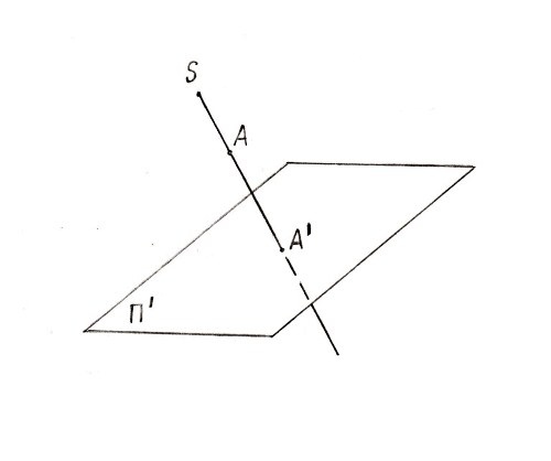
Located in the space plane P’, the point S – the center of projection and an arbitrary point a (figure 1). If through the point S and draw a line to the intersection with the plane P’, you get the point A’. It is a projection of the point A in space to plane projection P’. Video SA is called the projecting ray. The drawing is built by design, is a projection.
Located in the space plane P’, the point S – the center of projection and an arbitrary point a (figure 1). If through the point S and draw a line to the intersection with the plane P’, you get the point A’. It is a projection of the point A in space to plane projection P’. Video SA is called the projecting ray. The drawing is built by design, is a projection.
2
If the projecting rays are perpendicular to the plane of projections, such projections are called rectangular.
When determining the position of a point in space by its projections of one plane of projection is not enough. Therefore we introduce an additional second plane. The most acceptable location of the planes of projections in which one of them vertical and the other horizontal.
When determining the position of a point in space by its projections of one plane of projection is not enough. Therefore we introduce an additional second plane. The most acceptable location of the planes of projections in which one of them vertical and the other horizontal.
3
The plane of projection is horizontal, called the horizontal plane of projections and denoted P.
A vertical plane located in front of the observer, is called a frontal plane of projections and denoted P. P plane perpendicular to the plane P (figure 2). Video mutual intersection of two planes of projection is called the axis of projection x₁₂.
A vertical plane located in front of the observer, is called a frontal plane of projections and denoted P. P plane perpendicular to the plane P (figure 2). Video mutual intersection of two planes of projection is called the axis of projection x₁₂.
4
Assuming that the plane of the drawing coincides with the front plane of projection, the horizontal plane of projections P perpendicular to the plane of the drawing.
5
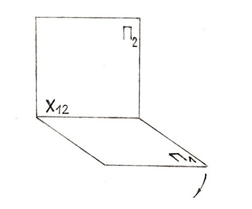
Plane P and P must simultaneously coincide with the plane of the drawing. For this plane P rotate around the axis x₁₂ to align with the plane P (figure 3).
6
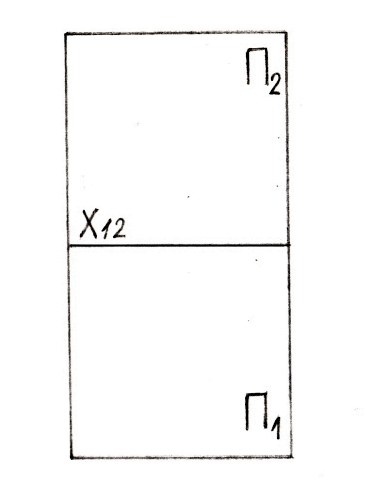
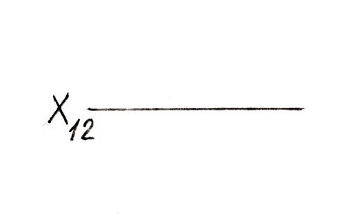
The drawing is not indicated plane P and P, and is only horizontal line – axis of projections x₁₂ (figure 4).
7
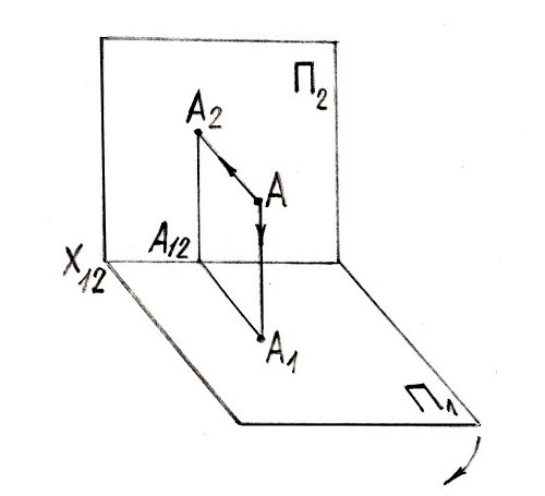
Point a is located in the system of planes P and P (figure 5). To construct the projections of point A are projecting rays are perpendicular to A P and A perpendicular to the plane P. A – front projection of the point A, and A – the horizontal projection of the point A in space.
8
Rectangular projection of the point into two mutually perpendicular to the plane of projection is called orthogonal projections.
A – distance from point to plane P; A=AA.
A – distance from point to plane P; A= AA.
A – distance from point to plane P; A=AA.
A – distance from point to plane P; A= AA.
9
The drawing, which shows a projection of the point combined with a single plane, called a complex drawing (apuram). On a complex drawing horizontal and frontal projections of one point located on the vertical lines of communication AA perpendicular to a projection axis x₁₂.
10
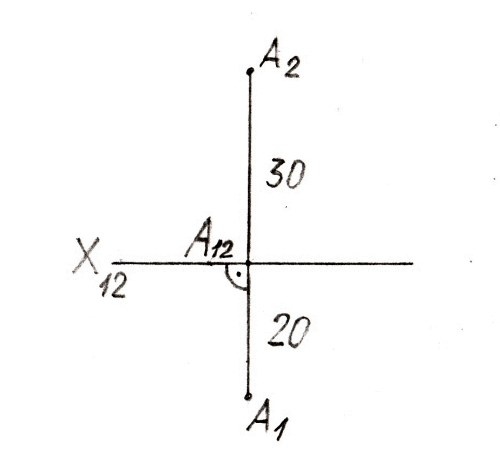
Example. To build a complex drawing point And remote from the plane P 30 mm and from the plane P – 20 mm (figure 6).
11
Guide axis x₁₂. Perpendicular to the axis draw a line vertical connections. Off-axis projections put the cut to 30 mm – get a front projection of point A. Similarly postpone the cut AA equal to 20 mm, – get the horizontal projection of the point A
The constructed image is the desired complex drawing and determines the position of the point A in space.
The constructed image is the desired complex drawing and determines the position of the point A in space.